Fact Sheets
To account substantially to a better understanding of seismic hazard and risk in Europe, several questions have to be answered. With our fact sheet series, we address key questions SERA is challenged with and present preliminary results.
Click on the questions below in order to gain insights to crucial terms and concepts in seismology and earthquake engineering.
Serie #1: Basics in Earthquake Engineering
Seismic hazard is the probability of an earthquake occurring at a given location, within a given window of time, and with a ground motion intensity measure i.e. peak ground acceleration, exceeding a given threshold. The assessment of seismic hazard essentially comprises two steps, (a) the definition of the seismic action in the framework of European and National Seismic Codes and, (b) the evaluation of the seismic risk at local, regional or national scale. For evaluating the Seismic Risk (R) of physical and non-physical elements at risk, i.e. socio-economic features, one needs to combine the evaluation of Seismic Hazard (H) with the Exposure (E) of the elements and, most importantly, the Vulnerability (V) of each element.
Realistic seismic hazard assessment requires good knowledge of historical and recent seismicity (see figure above) and the neotectonic regime, namely the seismically active or seismogenic faults (see map of faults in the EuroMediterranean area). Such information will allow defining, along with other multidisciplinary data (e.g., geological, geodetic, satellite), those sources capable of producing damaging earthquakes. In addition, well calibrated/validated methods and models may be developed, with the aim to predict the intensity of a given ground motion measure at a specific site, from an earthquake of specific magnitude and distance from the site. Local site effects modifying the seismic actions could be also included in the seismic hazard assessment. Several seismic sources contribute to the seismic hazard in an area and their combined effect is mapped as probabilities in seismic hazard maps.
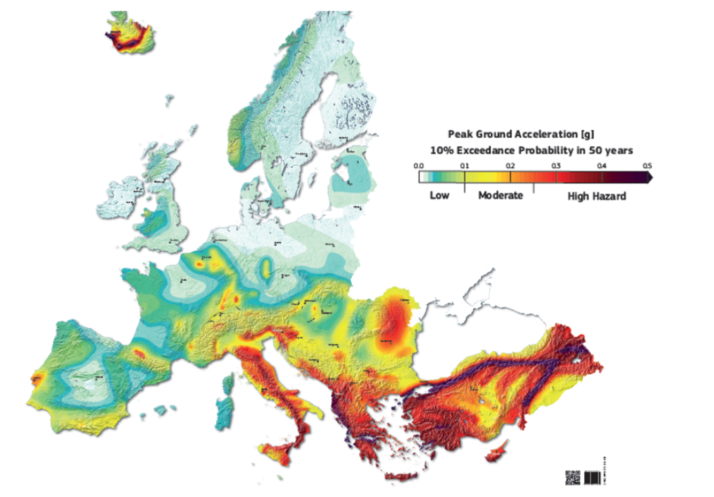
European Seismic Hazard Map showing the probability of peak ground acceleration exceedance of 10 % in 50 years (SHARE Project)
Risk assessment is a key component of the complex disaster risk management activity, which comprises identification, evaluation, and prioritization of risks and should be understood in a multihazard/multi-risk perspective. It can be carried out at local, regional or country level by national authorities and/or governmental agencies according the corresponding policies and mandates.
European policies on disaster management aim at achieving a high level of mitigation to protect people, but also of the environment and property, including cultural heritage, against all kinds of natural and man-made disasters. This is achieved through cooperation and coordination among countries, together with regional and local authorities, on prevention, preparedness and response actions. Prevention is more cost-effective and can be even a driver for economic growth. It is therefore attracting more attention as part of the disaster management cycle.
Fourth most common hazard
In the most recent national risk assessments prepared by the countries participating in the Union Civil Protection Mechanism, earthquakes are the fourth most common hazard assessed after flooding, extreme weather and forest fires. 19 countries (Austria, Bulgaria, Croatia, Cyprus, France, Germany, Greece, Hungary, Iceland, Italy, Malta, Norway, Portugal, Romania, Serbia, Slovakia, Slovenia, Spain and Sweden) performed seismic risk assessment and in some cases considered cross-border risk and cascading effects such as tsunami, landslides, disruption of infrastructure and industrial accidents. In the global context, the Sendai Framework aims to prevent new and substantially reduce existing disaster risk and losses, applying measures such as the reduction of vulnerability and exposure. Inclusive, safe, resilient and sustainable cities feature among the Sustainable Development Goals.
To understand the following, some definitions are appropriate. Disaster risk comprises three elements: hazard, exposure and vulnerability. Hazard is the dangerous phenomena, being the source of potential harm. Exposure refers to people, property, systems or other elements present in hazard-prone areas. Vulnerability represents the susceptibility of an element at risk of being adversely affected by natural phenomena.
Definitions
Disaster risk is the potential loss of life, injury, or destroyed or damaged assets which could occur to a system, society or a community in a specific period of time. Disaster risk assessment is the qualitative or quantitative approach to determine the nature and extent of disaster risk by analysing potential hazards and evaluating existing conditions of exposure and vulnerability that together could harm people, property, services, livelihoods and the environment. Finally, disaster risk management is the application of disaster risk reduction policies and strategies to prevent new disaster risk, reduce existing disaster risk and manage residual risk, contributing to the strengthening of resilience and reduction of disaster losses.
Seismic risk could be defined as the likelihood of damage from earthquakes to a building, system or the entire society taking into account social, economic and environmental consequences. It is normally obtained from the hazard of the site/region and from the vulnerability for the different types of buildings or constructions and quantified in terms of losses. Methods to assess and mitigate seismic risk are briefly described in the following.
Early warning systems rely on the difference of arrival times between warning messages and destructive shaking waves. The former are transmitted almost instantaneously when triggered by an earthquake, whereas the latter may take seconds to minutes to arrive at a location. People and automated systems may use this short time delay to activate measures to protect life and property.
Near real-time loss assessment systems provide rapid estimates of ground motion, damage and losses following a seismic event, once its magnitude, time of occurrence and location is known. PAGER is a well-known near real-time loss assessment system, which provides estimates of human and economic losses at a global scale.
Earthquake scenarios are used to elaborate seismic risk emergency plans, to model seismic losses, to evaluate the seismic actions needed for the design of civil engineering structures, etc. An example of an earthquake hazard scenario is the maximum probable or credible earthquake, i.e., the largest earthquake that is reasonable to be expected in a region. In the last decades several tools have been developed for the assessment of loss scenarios, or for the evaluation of earthquake impact on critical infrastructures, such as, HAZUS, CAPRA, AFAD – RED, EQIA, SELENA, GEM OpenQuake, RASOR, or RapidN.
Probabilistic seismic risk assessment takes into account all possible earthquakes that may affect a site and a probabilistic estimation of damage and losses, including relevant uncertainties. Results are obtained in terms of risk metrics, such as loss exceedance curves or averaged earthquake losses. Thus, seismic risk may be described, among others, by (i) the probability that various levels of loss will be exceeded, (ii) by average annualized earthquake losses, (iii) or by average annualized earthquake loss ratio (AELR). AELR is a useful metric to compare the relative risk across different regions, since it is normalized by the replacement value.
Importance of standards and building regulations
It is worth emphasising the importance of standards and building regulations in achieving more resilient and sustainable buildings. The EN Eurocodes that are a series of 10 European Standards, EN 1990 - EN 1999, providing a common approach for the design of buildings and civil engineering infrastructures, have proven to be a useful mechanism to mitigate seismic risk and to reduce losses in future earthquake events.
Among other activities, SERA provides access to the largest collection of high-class experimental facilities for earthquake engineering in Europe for researchers to test new technologies, methods and materials to reduce the vulnerability of the built environment and eventually increase the resilience of societies.
Earthquakes are one of the most hazardous natu-ral threats to life and property – their effects are often causing high social, economic and environ-mental costs. The share of civil engineering structures in the earthquake–inflicted damage is large, justifying that “collapsing structures kill people, not earthquakes”. Earthquake excitation is a very intricate loading condi-tion as it:
- occurs unexpectedly in space and time;
- varies considerably in intensity even at short dis-tances;
- is composed of randomly changing cycles of varying amplitude;
- may include vibration components in more than one direction;
- acts in tandem with (part of) the vertical loads;
When seismic waves reach the foundation of a struc-ture, the latter follows soil displacement and due to the “cyclic” nature of the input waves, the whole structure starts vibrating in (generally) three directions.
Structural geometry is decisive
Although concrete and masonry buildings are stiffer than their counterparts made of steel, they cannot be considered as rigid bodies – had that been so each point on it would move in the same amount as the ground. Concrete and masonry buildings indeed deform, dis-place and rotate due to their flexibility. Their behavior depends mainly on the fundamental period of vibration (function of the stiffness of the structural system, its mass, and its total height).
Structural geometry is very decisive for the type (mode) of vibration of a structure: while a simple, symmetric structural configuration results in a rather uniform ac-tion throughout the structure, structures of irregularly configured layout (T-shaped/L-shaped structures or structures with vertically offset floor levels) tend to con-centrate deformation demands on few locations, thus lending members to higher damage. Therefore, the same seismic excitation affects buildings differently; for example, tall buildings tend to amplify the motions of longer period earthquake excitation components. Adja-cent structures, vibrating at their own period, may also affect the vibrational response of a neighboring building via the additional deformations they impose through pounding.

At low levels of excitation, structural members behave elastically: when the seismic motion stops, the structure returns to its initial position without any or with only minor damages to non-structural elements (e.g. parti-tion walls). With increasing amplitudes of seismic mo-tion, the deformation level of all building elements is enhanced as well. Structural members may accommo-date the deformations exerted (displacements and rota-tions) as long as the deformation demand does not ex-ceed the members’ capacity in terms of relevant engi-neering properties (drift, strain, angle of rotation, etc.). When this threshold is surpassed, damage occurs.
Damage of load-bearing (structural) elements is a form of energy dissipation within the structure (more decisive than the inherent material/structural damping), but also the reason for a decrease in material strength. The cy-clic nature of shaking is very detrimental for most com-mon construction materials (i.e. concrete, masonry and steel), particularly when they are exposed to defor-mations of large amplitude. Among others, the follow-ing processes lead to degradation of material perfor-mance: opening or closing of cracks in concrete/masonry, yielding of steel, deformation of connections/nodes in steel structures, transition of reinforcing bars from compression to tensions and vice-versa, and lat-eral expansion of concrete under axial compression.
Plastic state
With increasing amplitude of motion, cracks propagate and reinforcement enters in its yielding (plastic) state. At this point, damage results in a continuous modifica-tion (reduction) of the stiffness and thus of the dynamic characteristics (vibration period of vibration) and defor-mation of the structure during shaking.
Even after the seismic motion ceases, structures (due to their kinetic energy) continue to vibrate. Due to the in-herent structural damping and the energy consumption in the damaged areas (hysteretic damping) the ampli-tude of free-vibration motion continuously decreases, until the structure stops. With increasing extent and severity of damage, structures develop permanent de-formations and, thus, do not attain their pre-earthquake geometry. The degree of damage, for the same seismic motion, varies from structure to structure. Structures built before the advent of modern design codes are par-ticularly vulnerable ones. The damage that develops in a structure can be either contained within few elements (creating the conditions for possible collapse) or, may propagate to larger number of elements (allowing, thus, enough margin till the relevant member resistance). This observation is particularly useful and forms the un-derlying principle in regulatory documents.
After a seismic event, depending on the expected im-pact on the structural stability, the authorities conduct a screening procedure in order to characterize the dam-aged structures as useable, useable after repair or to be demolished.Modern codes of practice (e.g. Eurocodes) include ap-propriate approaches both for designing new structures and for assessing or retrofitting existing ones.
Avoiding structural collapse
Code pro-visions for new structures promote – as economically more viable – the design of flexible and strong structures. Their main target is to avoid structural collapse and, while they do allow some damage to develop, they strive to preclude uncontrollable or non-repairable damage. With this compromise, modern societies, may-be with the exception of critical structures, consent to some degree of acceptable risk, as they do in other are-as. Nevertheless, users may opt for a no-damage ap-proach and then modern technologies like seismic isola-tion or active control may be employed, certainly at much higher costs.
In order to study the effects of earthquake actions on a structure, performing shake table tests is the most realistic research approach. This article describes how the testing of a building structure on a shake table is performed and which are the outcomes and benefits of this type of experimental test. A shake table system is composed of several compo-nents, comprising mainly the hydraulic pumping system, servo-valve controlled actuators, the shake table platform, and the digital control system. A simple uniaxi-al shake table platform and its components is depicted in the picture.

When planning a shake table test, one of the first deci-sions is related to the geometric scale of the model with respect to the prototype (real structure). When the ca-pacity of the shake table system is not able to withstand the dimensions and weight of the real structure, a re-duced scale model has to be used and dynamic simili-tude laws should be adopted based on the Cauchy and/or Froude numbers. The former relates the inertial forces to the elastic resisting ones, while the latter relates the inertial forces to the gravity ones.
After defining the typology, geometry and materials of the model, the latter is usually built outside the shake table and then transported onto it, either by a moving crane or over roller supports. The model is then fixed on the table and instrumented.
Collecting data during test
Given the plethora of phenomena intervening on the dynamic response of a structure, it is important to collect accurate and extensive sets of data during the shake table test. This implies adopting an instrumentation plan for measuring different physical quantities using availa-ble technology (displacement transducers, accelerome-ters, strain gauges, load cells, optical measurement de vices, etc.), and placed at the locations where significant response quantities are foreseen and where damage is expected to occur. Typically, in a shake table test, the sensing devices should be able to measure accurately at frequencies up to 100 Hz and should be sensitive enough to measure small values of the response quantities with a high signal-to-noise ratio, while being robust enough to measure up to the amplitude range of interest. A typical instrumentation layout for a specimen and its application is shown in the picture next.
In shake table tests one may also be interested in simulating the behaviour of non-structural elements, which often represent a significant portion of the economic losses due to seismic activity. Shake table tests are performed in stages of increasing intensity of the seismic input, intertwined with dynamic identification stages for assessing the evolution of the dynamic properties of the specimen.
Check with dummy specimen
At each stage of seismic input, the shake table controller has the objective of achieving a target table motion by continuously correcting the motion of the actuators through feedback readings and real-time comparison between executed and target motions. Usually, the initial drive motion for a given seismic input stage is already the result of a previous tuning process using the shake table system with a dummy specimen. Such dummy specimen should represent the actual specimen’s mass, mass-distribution and (possibly) its stiffness with the aim of calibrating the actuators' input motions so that they match the required target input and incorporate the dy-namics of the coupled shake table—specimen system. Nevertheless, the dummy specimen is often not capable of fully representing the real specimen's dynamics and its degradation due to damage. The real-time control is thus very important for ensuring a shake table input motion is close to the target one. Target and achieved shake table motions should closely match during all testing stages. The dynamic identification between test stages is very useful to quantify the degradation of the model in terms of the decreasing natural frequencies of vibration and increasing modal damping.
Upon cracking, yielding, and general damage phenome-na, the structure becomes more flexible – decreasing its natural vibration frequencies and dissipates more energy during vibration due to friction and hysteretic behaviour. This results in larger equivalent damping and a shorter settling time after the ground motion input ends. The quantitative assessment is an important complement to the visual inspection of damage in the specimen. Dam-age assessment of a stone masonry model using both methods is shown next-note the decrease in modal fre-quencies for the first two modes of vibration and the crack pattern observed at the end of the test.

Assessment of damage in a masonry model through dynamic identification (top row) and crack pattern (bottom row) representation.
The measurement of accelerations, forces and displace-ments, together with the abovementioned damage assessment procedures allows for the interpretation of the specimen's dynamic behaviour. For this, global force-displacement plots recorded during a shake table test for a given specimen, along with a summary of the dam-age limit states attained for each displacement demand, may be employed. During a shake table test, it is important to be able to characterise the full spectrum of damage limit states, from the initial cracking up to the collapse of the specimen.
This experimental technique has been very important in the past and continues to give important contributions to our understanding of the structural behaviour and seismic strengthening, while also accompanying the de-velopment of new technologies for testing and data acquisition. Furthermore, the seismic qualification of critical equipment and the development and calibration of numerical tools for simulating the dynamic response of structures, rely heavily on the results of shake table tests. Concluding, the development of seismic mitigation techniques, materials and devices have in shake table testing the ultimate proof of concept before being adopted in real structures.

Series #2: A Closer Look into the Projects
Thirty years ago, when people felt a tremor, they went to their phone to contact the seismological institute in the area. Today, eyewitnesses turn to social media (Twitter, Facebook, websites, smartphone apps) and the phones no longer ring in our laboratories! These online reactions of eyewitnesses occur typically only a few seconds after the ground shaking and are both a challenge and an opportunity for the seismological community. A challenge because they express an urgent desire for information from the public which, in order to be met in a timely manner, leaves little time for human intervention.
Yet how to balance between the rapidity of automated data analysis and the reliability of the disseminated information? Different strategies are being developed in Europe and beyond depending on the level of seismic hazard, whether the institute is staffed 24/7, etc. Despite these challenges, the use of social media is also an opportunity for the seismological community to better serve societal demands associated with earthquake risk, and an opportunity to collect data of scientific interest at little cost. This is the aim of LastQuake, a multichannel information system comprising of different websites, a Twitter quakebot and a smartphone app.

Reaction of eyewitnesses following a felt M 3.1 earthquake as observed through LastQuake app launches (red), EMSC website for desktops (blue) and the one for mobile devices (green). Visits start launching the app within a dozen seconds of the earthquake occurrence offering an efficient and fast way to automatically detect felt earthquakes.
LastQuake automatically detects the online reaction of eyewitnesses to global earthquakes, reports these reactions and invites them to share their experiences. By doing so, at least 100 000 felt reports are collected each year describing the local level of shaking or damage, half of them being collected within 10 minutes after a specific earthquake. Data is curated and collated with traditional seismic data to continuously improve information prod
ucts. Following requests from users, LastQuake also offers safety tips (“do’s and don’ts after an earthquake”), which together with improved situation awareness can contribute to risk reduction. It also fosters discussion with society, raises awareness of seismic risk and extends existing collaborations in seismology with the social sciences.

Map of the 120 000 individual reports collected in 2018. It illustrates the global audience of LastQuake information system. Half of the reports were collected within 10 min of the earthquake occurrence.
What about the advantages for the seismological community? A global database of felt reports is collected at little cost. Τhese can provide constraints rapid assessment estimates (D. Wald at USGS is testing the integration of EMSC felt reports to constrain global shakemaps). As the database grows, new research topics are appearing (i.e. definition of regional intensity prediction equations, site effects mapping, vulnerability studies).
This dataset of felt reports has joined the other data and products collated at EMSC (rapid earthquake parameters, focal mechanisms, EventID, Flinn-Endahl regions, rupture models) and the data is now available through webservices which are themselves part of the EPOS initiative (European Plate Observing System). LastQuake represents a win-win strategy for both the public and seismologists.

Understanding seismic hazard is essential for pre- and post-earthquake mitigation actions, including design rules of new buildings, identification and strengthening of vulnerable buildings, land use, development of preparedness action plans with involvement of decision makers, engineers, practitioners and academia. Seismic hazard indicates the likelihood of earthquake related phenomena (ground shaking, tsunami, landslides, liquefaction) in a region and provides an essential input to understand seismic risk, the likelihood of damage and loss for a region. In turn, the analysis of seismic risk combines information on seismic hazard, the natural phenomena, with information on the elements exposed - buildings, infrastructure, or people - and their vulnerability to earthquake effects (i.e. ground shaking).
The European Facilities for Earthquake Hazard and Risk (EFEHR) integrates the community resources for earthquake hazard and risk in Europe. A newly developed web-platform is the core gateway to scientifically credible seismic hazard models, related data, software and expertise which are relevant for assessing seismic hazard in Europe. The main services (databases and webplatform) of EFEHR are hosted at ETH Zurich and operated by the Swiss Seismological Service (SED). The management of EFEHR includes coordination of specialized activities as well as reporting, controlling, communicating, promoting acquisition of third-party projects and supporting industry relations. EFEHR is one of the three thematic core-services for seismology in the European Plate Observing System (EPOS) infrastructure.
The EFEHR web platform (www.efehr.org) provides open access to seismic hazard and risk models. The EFEHR web-platform is the public interface of a complex system connecting databases of relevant datasets, inputs, outputs and model results with the functionality to access, visualize, and download the following hazard outputs: seismic hazard maps, seismic hazard curves and uniform hazard spectra. Web services are fully operational since 2013. The risk services are under development. In terms of available hazard models, the EFEHR web platform distributes the seismic hazard models for:
- The 2013 European Seismic Hazard Model (ESHM13, Woessner et al 2015)
- The 2014 Earthquake Model of the Middle East (EMME14, Giardini 2018)
- The 2015 Swiss Hazard Model (SuiHaz15, Wiemer et al 2015)
- The 1999 Global Hazard Map of the Global Seismic Hazard Assessment Program (GSHAP, Giardini 1999)
The EFEHR web platform provides a single access point for data, models and results. No user authorization is required.
Core Activities
- Provide open access to state of the art, authoritative and reproducible information on earthquake hazard and risk, harmonized across Europe and targeted to a wide range of stakeholders.
- Enable national and local hazard and risk assessment by providing access to the software, data, models, and expertise required for contemporary hazard and risk assessment.
- Conduct periodical reviews of the European hazard model and results, provide updated models when needed, thus moving to a “living” and dynamic seismic hazard model.
- Promote best practice and knowledge exchange within the research community.
- Review and quality control contributions to relevant databases for PSHA (e.g., active faults, site, EQ catalogues, GMPE, site).
- Promote standardization and connection to practitioners (e.g., Eurocode 8)
- Integrate with the engineering community in order to ensure a seamless transition from hazard to risk (exposure, vulnerability).
- Advise industry, national and regional governments.
- Support panels of experts.
- Provide access to computational capability.

Plain (smooth) bars are not used anymore as primary reinforcement of new concrete structures. The building codes of most countries have banned them from such a use for a long time now. Nonetheless, being common in old structures which are evaluated for rehabilitation, they enjoy the world's structural engineering community's renewed interest. Nevertheless, still little is known about how structure with plain bars behave in a strong earthquake.
The seismic behavior of a 1:1.5 scaled three-story twobay Reinforced Concrete (RC) frame with smooth bar reinforcement was experimentally studied. The frame was designed for gravity loads and lacks any seismic design or detailing. An important parameter examined was the behavior of lapped column bars in comparison to continuous bars. Thus, two opposite columns of the specimen were constructed with continuous bars and the remaining four using spliced longitudinal bars, as per the standard design and construction practice used by older codes and designers.
The columns had eight 12 mm plain vertical bars (at corners and mid-side), 6 mm perimeter ties at 150 mm centers (also inside the joints) with a 90-deg hook at one corner. Beams had two 16 mm deformed bars at top and bottom, continuous through interior joints and anchored at the corner ones with 90-deg bends; ties of 8 mm deformed bars at 100 mm centers had a 135-deg hook at one corner. Additional dead loads of about 70 kN on each floor slab were placed to simulate the part of the permanent/ useful loads acting concurrently to the earthquake.

Three-story, nearly full-scale specimen in STRULAB TA facility (arrows indicate columns with continuous reinforcement – in all others, bars are spliced)

Initially, a free-vibration test (snapback-type) was conducted to determine the dynamic properties of the specimen. The response spectral acceleration and displacements indicate a fundamental frequency of approximately 3.95 Hz in the X-direction. The structure was then subjected to lateral loads applied along the long side of the structure. A prescribed history of cyclic roof displacements of increasing amplitude was applied by the actuator at the top. The actuators at the two lower floors were slaved to the top one so that an inverted triangular pattern of floor forces was applied, anchored to the force produced in the top actuator by the prescribed history of roof displacements. The horizontal deformation pattern comprised displacement cycles of +/-50mm amplitude at the top of the structure. Several response parameters (forces, displacements, local deformations, strains) were acquired via a network of more than 100 transducers.
During the tests, the first and second story clearly yielded in the first half-cycle of loading, while overall yielding of the third story didn't take place until the end of the test. The inverted-S shape of base shear vs. top displacement loops is typical for cyclic bond-slip behavior and shows that the hysteretic behavior of all stories is dominated by bond along the column bars.
The top and base sections of all six columns in the two lower stories opened up from the first load cycle, while hairline diagonal cracks at the exterior face of every beam-column joint - with the exception of those at the roof - opened during this phase of testing, but were not visible after it.


In the next phase of testing, the top and bottom part of three columns (two with lap-spliced bars and one with continuous ones) and the respective joints at first and second stories were retrofitted with two plies of epoxyglued carbon-fiber reinforced polymer (CFRP) sheets providing of adequate anchorage.

FRP retrofitted frame
Α second cyclic test took place up to a top displacement of 150mm. The test showed that neither the lap splices nor the Fiber Reinforced Polymer (FRP) wrapping of the column end regions had a systematic effect on the behavior of columns. The FRP wrapping had only little impact on the column response. The reason is that the FRP wrapping slightly increases the yield moment and the stiffness of a member, but it drastically improves the flexural deformation capacity. In this case, however, deformation capacity was beyond the deformation demands.
Cracking at the interfaces of columns and joints but also at the interface with the foundation beam were more obvious after this second test at all interfaces of the first floor.

Base shear vs top displacement of the initial and the retrofitted frame
A final monotonic test was conducted to define the capacity of the retrofitted frame, pushing it to 200mm. After removing the - already detached - FRP wrapping from joints and column ends, larger cracks at the interfaces became evident. The same applies for the diagonal cracking in joints which reached a width of 10 -20mm.
Overall, structural performance was not adversely affected by the use of plain bars; in fact, the large fixed-end-rotations due to slippage of column bars made possible the development of appreciable chord rotations and interstory drifts, without serious damage or residual deformations. Despite that the hysteretic behavior of all stories in the frame was governed by the bond along the column bars, cyclic strength decay - typical of bond-slip loops - was not observed. Apart from the visible residual cracks at column end sections, the rest damage inflicted by cyclic loading had little to do with the use of plain bars in the columns. Column deformations were concentrated at flexural cracks at the top and bottom sections, thanks to slippage of the plain bars.
Neither the lap splices nor the FRP wrapping of the column end regions were found to have a systematic effect
on the behavior of columns.
The cyclic behavior and performance of the frame may be considered satisfactory, apart from the diagonal cracking of joints, which had little to do, though, with the plain bars in the columns.


Surface morphology as well as soil stratification and composition are decisive parameters influencing seismic motion time histories recorded on the earth surface. To study these effects at the Volvi basin (Thessaloniki, Greece), geological data from the EuroSeisTest experimental station on site were employed to construct a 3D numerical model of the basin.
The investigation targeted at exploring how soft sediments affect the dispersion of the earthquake ground motions and at assessing its impact on the 3D geological interfaces as well as on the spatial fluctuations of the mechanical properties.
A source-to-site computational model is built, configured as a three-dimensional soft basin embedded in bedrock. The transient wave-field is computed applying the 3-D spectral element method in elastodynamics. To enhance compositional efficiency, the effort is divided over large parallel supercomputers. Earthquake simulations at regional scale (tens of kilometers) are performed, including the irregular edges of the basin.

Layout of the spectral element model of the Mygdonian basin
The spatial modification of the soil shear modulus is integrated into the model as a multi-variate stationary random field. The effect of soil heterogeneity is compared to the homogeneous soil. This allows to assess the influence of the soft basin behaviour on the ground motion.

Example of the heterogeneous shear modulus
The effect of the soft basin is studied in terms of time series recorded at the soil surface and in terms of wave motion coherency. The basin scatters the wave motion propagated from the hypothetical fault, trapping the radiated energy due to the great basin-crust large stiffness contrast. In contrast, the soil heterogeneity acts at a smaller scale, inducing local scattering which is poorly visible in this low frequency range. As future developments, the softer basin layers will be included in the analysis, along with an increased frequency range, allowing to evaluate the role of the soil heterogeneity at higher frequencies.

Εarthquakes are one of the most destructive and unpredictable events of nature with catastrophic consequences for both people and built environment. Secondary triggered effects can strike further an already weakened community, i.e. ground shaking, surface faults, landslides and tsunamis. In this respect, also fires following earthquake (FFE) are a considerable threat. They can be widespread both at the building level as well as at a regional level within the area affected by ground shaking due to damaged gas lines, failure of electrical systems etc. together with the failure of the compartmentation measures.
Such catastrophic events also cause damage to structures and impact local, regional and sometimes even international economies in the long-term. The reliable prediction of nonlinear structural behaviour and the failure mechanism during severe seismic or FFE events has proven to be an extremely difficult task. Experimental research therefore is critical towards better understanding and prediction of the seismic and fire response of structural and non-structural components. There are different experimental techniques that can be used to test the response of structures to verify their seismic and fire performance:
- Numerical simulation of the structure: the real behaviour of the elements/structures may be very different.
- Physical tests on single components: for example, tests on single components subjected to standard heating curves or partial subassemblies. They offer significant information for the understanding of seismic and fire performance of specific structural elements, but they do not provide insight on the interaction between the fire development or the seismic actions and the whole structure.
- Physical full-scale tests of the whole structure: For example, by using an earthquake shake table, where structures are excited in such a way that they are subjected to conditions representative of true ground motions caused by an earthquake. However, large-scale structural seismic or fire tests are expensive and need specialized facilities.
- Physical small-scale test of the full structure: due to the limitation on the size and capacity of facilities, structures are typically tested on a reduced scale or a highly simplified model is used. Testing with reduced scales or simplified models has the downside of not adequately representing the response of the full-scale structure which questions the validity of this type of test.
In order to overcome such limitations, Hybrid Simulation (HS), which is also called pseudo-dynamic test method, represents a tempting approach.

Kobe Earthquake 1995 (Japan)
Hybrid simulation, extensively investigated in the seismic domain, is a hybrid procedure that combines classical experimental techniques with online computer simulation for cost-effective large-scale testing of the structure under simulated loads. In detail, hybrid simulation facilitates the study of structural response by experimentally testing only the critical portion of the structure (for example the part of the structure being studied or some part, where it is difficult to simulate its behaviour), while the rest of the structure is modelled numerically in a real-time computer. The hybrid model of the prototype structural system combines numerical and physical substructures (NSs and PSs).

Example of physical substructure
At each step of the analysis, the governing equation of motion is solved, similar to pure numerical simulations using a time stepping integration. The calculated displacement demands are then sent to the laboratory and applied to the physical substructure using computercontrolled actuators while the numerical portion is analyzed in real-time. The resisting forces (typically axial and shear reactions and sometimes also moment reactions) are measured and sent back to the computation solver to calculate the displacements corresponding to the next time step. This is an iterative process and it is repeated until the time-history loads (like ground motion, temperature increment) are concluded.
Geographically distributed hybrid testing is one recent concept that has been developed from the use of substructuring techniques and benefited from technological advances in data transfer and computing. The concept of geographically distributed testing is that individual substructures do not need to be within the same facility and do not need to be in the same laboratory, but can be linked by methods of data transfer with minimal latency between the laboratories, like RTC (Real-Time Communications).
For the experimental substructure, one or more laboratories with different facilities can be chosen and used. In terms of the numerical portion of the hybrid simulation, there are also benefits in allowing for the use of more powerful computers or even supercomputing facilities to run the hybrid simulation test since those supercomputers do not need to be in the same laboratory.


Industrial facilities like chemical, oil and gas plants can trigger severe environmental and human consequences when subjected to seismic action. Moreover, such consequences are not always limited to the facilities themselves but possibly affecting nearby communities, infrastructures and plants. As a matter of fact, earthquakes can cause exceptional human and economic losses in the case of natural-technological, or NaTech events. Some recent examples of such events are petrochemical plant fires during the Izmint earthquake of 1999, environmental chemical contaminations following the Sichuan earthquake of 2008 and the nuclear and radiation accident caused by the 2011 Fukushima earthquake.

Oil refinery in Ichihara after Fukushima earthquake
In order to prevent serious consequences of NaTech events, the European directive Seveso-III (Directive 2012/18/EU) explicitly states that safety reports for industrial plants involving hazardous substances should include “detailed description of the possible majoraccident scenarios and their probability or the conditions under which they occur”. The methodology of performance-based earthquake engineering (PBEE) can compute the probability of failure under seismic action and is
generally applied to quantify seismic risk of nuclear power plants. However, this framework is not so commonly adopted for petrochemical plants.
As a matter of fact, industrial plants often encompass numerous components with different associated risks to external actions. One of these components are pipelines, widely adopted in petrochemical facilities and demonstrated to be vulnerable to seismic action. Common vulnerable components of industrial pipelines are bolted flange joints, tee joints and piping bends or elbows. Among realistic failure scenarios, leakage or loss of containment of hazardous substances is one of the possible effects of pipelines failure and can severely affect the environment and the nearby communities.
Focusing on pipeline components, bolted flange joints are quite complex since they are highly confined, statically indeterminate systems and because they involve a high degree of non-linearity. As a result, it is difficult to correctly estimate their resistance and stiffness, as also the threshold of leakage

Bolted flange joint from the tank-piping system under study
Among industrial piping components, tee joints are one of the most critical components due to stress concentration. Considering the specific case of petrochemical plants, the event of loss of containment in tee joints can generate severe consequences. However, tee joints’ seismic resistance is poorly investigated and, consequently, related regulations prescriptions lack of details and accuracy which can lead to an inefficient design and incorrect safety assessment.

Tee joint from the tank-piping system under study
Piping elbows are a critical component in a piping system characterized by high flexibility, level of stresses and strains and a significant cross-sectional deformation. Since the goal of this experimental campaign is the investigation of the onset of leakage triggered by seismic action, particular attention is paid to pipe bends due to their vulnerability.

Piping elbow from the tank-piping system under study
Within the SERA project, we study the seismic response of a coupled tank-piping system by means of hybrid simulation. Specifically, the hybrid model of the system under study combines numerical (NSs) and physical substructures (PSs). In our case, the steel tank is the NS and the piping network the PS.


Experimental hybrid test setup
As a first step we define a seismic scenario associated to a geographical site by means of a probabilistic seismic hazard analysis. Then, based on this analysis we provide an adequate seismic input employing a stochastic ground motion model calibrated against coherent natural seismic records. Moreover, we carry out a global sensitivity analysis to reduce the space parameters of the stochastic model and we synthetize a large set of ground motions to be used in both experimental tests and finite element simulations.
In addition, two different finite element models, a refined high-fidelity and a faster low-fidelity model are calibrated against both hybrid simulations of the whole system and cycling tests of vulnerable components, i.e. piping tee joints and bolted flange joints.

Deep underground mining for metal resources, geothermal power production, exploitation of hydrocabons by fracking procedures or water reservoir impoundments are human technological activities which not only make the desired resources available to us but also may induce unfavorable side effects. These can be the triggering of micro-earthquake or large earthquake, landslides, rockfalls, and contamination of groundwater, just to name a few. These biased consequences of human actions on the natural environment cause numerous controversies which foster the need of objective information as well as scientific approaches for the understanding of the observed phenomena. Responding to these needs, the IS-EPOS platform for induced seismicity and anthropogenic hazard offers an Internet environment where relevant data sets (episodes) as well as software tools (applications) for scientific data analysis are available. Hence, the platform is dedicated to all users from research experts, over engineers from industry, governmental and political entities and, last but not least to the interested and concerned public. In the framework of the SERA project, the platform facilitates the direct virtual access to its resources. IS-EPOS platform is accessible through https://tcs.ah-epos.eu. The platform resources are open to all; however, the user has to go through a simple registration process, for statistical purposes.
Episodes: The collection of episodes on the platform gives a representative overview of available data on seismic processes linked to all types of inducing technological activities from water reservoir impoundments to deep underground mining. Such a collection facilitates e.g. comparative studies, where researchers want to see how specific parameters behave in other environments and conditions. No time consuming search is needed in this case as the platform offers a multitude of data from different environments. Each episode is composed of a time correlated collection of seismic data and data which represents the technological activity, which is the cause of the undesired observed process. Also included is relevant geodata describing the respective environmental constraints of the area where human activity and the seismic processes take place. The contents of an episode depend also on the availability and the decisions of the respective data suppliers. All episodes have a seismological catalog and most of them also event related or even continuous waveforms. Depending on the type of anthropogenic activity, industrial data can consist of water injection rates, water levels and volumes, mining front advances, injection pressures etc. among other monitored parameters. Geodata incorporates most frequently used models of mines, velocity models for seismic event location, deformation measurements, etc., all in georeferenced data. What can result from the combination of injection rates and seismicity event rate at a geothermal power production site is shown in the figure below.

In this figure, 3 different daily injection rates at The Geysers geothermal field are given: total injection rate (blue curve), individual injection rate for the well Prati9 (black curve) and Prati29 (red curve). Below the injection rates, the seismicity rate is given by a blue stem for each event. The vertical bars behind the injection rates indicate time periods of 50 days which have significantly increased (gray bars) or decreased seismicity rates in comparison with the preceding 50 day window. The moving windows overlap. The total amount of data comprises more than 7 years. Figure taken from Leptokaropoulos et al., 2017.
Applications: Apart from the data collection, the platform offers software tools called applications which are ready to use on the chosen data sets. It can be either used to quickly check if the episode is valuable for the study purpose or to run a complete study e.g. the statistical properties of a catalog or the mechanisms of small induced earthquakes. The applications’ list comprises software tools for data handling, data processing, resource management and visualization. Figure below shows a 3D visualization of the induced seismicity of Bobrek Coal Mine in the region of Silesia, southern Poland.

3D visualisation of induced seismicity (green dots) in Bobrek Coal Mine. The purple volume is reflecting the velocity model, the rose colored volume encompasses the mining area. Black cones mark the seismologicalstation sites.
Workspace: In order to apply software tools to selected data sets, everything has to be transferred to the user’s workspace. The episode data transferred to the workspace can be downloaded to the user’s personal IT hardware. The user can also upload own data for tests and analysis with the platforms’ applications. Another important feature of the workspace is that it simplifies and supports collaboration among users in common research projects. A share function facilitates the exchange of data and results via notifications through the email accounts of the participating users.
The IS-EPOS platform provides VA access to the platform resources which were granted and available at the time when the SERA grant agreement was signed. However, the platform’s resources have been continuously growing since then and the platform administration is opening access to everything that is possible. Below, some technical facts about the current status of the platform are given:
- Data Centers: Polish eNODE – CIBIS (Warsaw), French eNODE – CDGP (Strasbourg), collaborating Data Center KNMI.
- Data Providers: in total 28 episodes are on the platform from institutions of 10 different countries.
- Applications: 35 tested applications are available for users of the platform.
- Users: 878 users from 152 institutions worldwide use the platform.
Engineering seismology is the study and application of seismology for engineering purposes. On the one hand, this involves understanding the source, the size, and the mechanisms of individual earthquakes, as well as the frequency of occurrence of earthquakes over time. On the other hand, it also involves the understanding of how the ground motion propagates from the source to the site of interest, the characteristics of ground motion at that site, and how the ground motion must be evaluated for engineering design. Therefore, it is a link between earth science and civil engineering. A fundamental task for engineering seismologists is to access the information that lays behind seismic hazard and risk models. In the past decades, the amount of openaccess data has dramatically increased thanks to the advances in information technology and the momentum gained by European and national projects in developing infrastructures to host data and promote their interoperability. These circumstances resulted in significant improvements of dedicated thematic repositories and of the tools that facilitate the user to access data and services.
It was not until few years ago that any study related to engineering seismology needed the construction of project-related datasets which implied lookup procedures into local, often offline if not even on paper, repositories. Data lacked metadata, so that it was not easy to get familiar with their format before starting to use them. Data collection used to be very time consuming. Moreover, data were not standardized so that an additional work of format conversion was often necessary, which implied a waste of resources.
SERA-VA3 aims to overcome these difficulties of the past and wants to bring the data at the users’ fingertips. It offers access to reliable and extensive data sets and services for the community of engineering seismologist and other specialists. They include the European Strong Motion Database (ESM), the European Archive of Historical Earthquake Data (AHEAD), and the European Database of Seismogenic Faults (EDSF).
European Strong Motion Database (ESM)
ESM is a centralised collector of European strong motion data, with a magnitude threshold of seismic events equal to 4. It archives the waveforms recorded since 1969 by about 50 European seismic networks and provides endusers with quality-checked and manually processed waveforms. The database is updated daily with new waveforms and metadata. The service is distributed and regulated under the umbrella of ORFEUS (Observatories & Research Facilities for European Seismology) and is one of the pillars of EPOSseismology (WP8 - waveform distribution). Data are accessible through a user-friendly web interface, whereas peak motions are accessible through a dedicated webservice (e.g. USGS peak values).
European Archive of Historical Earthquake Data (AHEAD)
AHEAD collects and distributes bibliographic, macroseismic, and parametric data on nearly 5000 European earthquakes from 1000 to 1899 CE, as provided by regional and national data-centres and the literature, with more than 200 data sources (available as PDF or links). All the data are accessible through a dedicated, userfriendly web interface, and through standard and documented web services (FDSN-event, OGC WMS, OGC WFS). AHEAD also provides the parameters, together with the macroseismic data at their basis, of the European catalogue used for the ESHM (European Seismic Hazard Model) 2013, and its 2020 version that is being developed in the framework of SERA.

AHEAD: Web interface example for the earthquake parameters (left) and macroseismic data (right) available for the earthquake occurred on 5th of September 1886 at border between Italy and France.
European Database of Seismogenic Faults (EDSF)
EDSF was designed, developed, and compiled by many geoscientists in the framework of the EU FP7 Project SHARE (Seismic Hazard Harmonization in Europe). EDSF includes faults that are deemed capable of generating earthquakes of M≥5.5 and aims to ensure a homogenous input for earthquake hazard assessment in the Euro-Mediterranean area. EDSF distributes data about crustal faults and subduction zones. The current version of the database counts 1'128 records, totalling 63'775 km of crustal faults, from Iberia to Anatolia, and three subduction zones, known as Calabrian Arc, Hellenic Arc, and Cyprus Arc in the central and eastern Mediterranean Sea. All the data and metadata are accessible through a dedicated, user-friendly web interface, and through documented web services (WFS, WMS, CSW) following the OGC standard protocols.

EDSF: Oblique view (looking to northwest) of the Aegean region showing a selection of crustal faults and the slab of the Hellenic Arc subduction. This view was made by performing a spatial query on EDSF and importing the selected data on a desktop software.
These three databases are intrinsically diverse and were originally conceived as separate entities, therefore coordination and optimization efforts are being carried out in the framework of SERA VA3 to blend them together.
The starting point of the integration of the three services was the construction of a web portal that works as a unified access point (http://sera-va3.rm.ingv.it/) to the data and services. This portal not only guides the visitors to the three original database portals, but it is also meant to provide an enhanced navigation experience through the data. The webpages feature a glossary of technical terms that are commonly encountered within the domains of the offered services, whose definitions spread on all webpages and appear in a tooltip message when hovering the mouse on highlighted words. Integrated access to the data will also be provided through a map viewer.
Finally, in order to facilitate the creation and sharing of information, ideas, and career opportunities we attempt to create a virtual community using social media (Twitter: @sera_va3) to advertise new releases of data and services, and useful information about conferences or workshops.

ORFEUS is a collaborative non-profit foundation that promotes seismological knowledge in the Euro-Mediterranean area through the collection, archival and distribution of digital seismic waveform data, metadata and derived products. ORFEUS is one of the largest infrastructures in the world that provides seismological waveform data to the scientific research community in strong collaboration with European seismological observatories. The ORFEUS infrastructure is built around a networked system of European seismological observatories, data archives and services. ORFEUS is one of the three pillars of the Thematic Core Service for Seismology within the European Plate Observing System (EPOS Seismology).
Two Service Management Committees (SMCs) are established within ORFEUS to manage, operate and develop (a) the European Integrated waveform Data Archive (EIDA); and (b) the European Strong-Motion databases (SM).
EIDA transparently connects (currently 10) large data centers in Europe, including the ORFEUS Data Center. This unique, federated archive serves seismological data from permanent (>100) and temporary (>100) networks of broad-band sensors and strong motion sensors deployed in Europe and beyond through dedicated services.


Access to waveform data is secured by services: a web interface, standardized webservices, data quality services and the Station Book.
The ORFEUS strong-motion databases provide highquality automatic (RRSM) and manually processed (ESM) waveforms, peak-motions and engineering parameters for any earthquake occurring in the Euro-Mediterranean region, starting from M>=3.5 for automatic processing. Virtual access to seismological waveform data is provided through webservices, interactive services and clients.
Webservices:
- fdsnws-dataselect - FDSN standardized webservice for mini-SEED waveform data.
- fdsnws-station - FDSN standardized webservice for station metadata.
- eidaws-routing - EIDA standardized webservice for routing between EIDA services.
- eida-wfcatalog - EIDA standardized webservice for waveform metadata.
- EIDA federator - webservice for collecting data without a-priori knowledge of where data is hosted.
- EIDA authentication - webservice to provide tokens from a central authentication system for EIDA.
Interactive services:
- ORFEUS website - the landing pages for all information concerning ORFEUS, EIDA and services.
- EIDA GUI - the web interface to interactively search for and download data from EIDA.
- StationBook - the GUI to access all (available) information on seismic stations across EIDA.
- RRSM GUI - the webinterface to search for and collect strong motion products in near real time.
Clients:
- ORFEUS Data Center developed a number of specific clients (www.orfeus-eu.org/data/odc//) to display features like data latency, event waveforms and data quality parameters.
Series #3: A Closer Look into the Projects*
The structural design of steel flat-bottom ground-supported silos containing granular material represents a challenging issue. They differ from many other civil structures since the weight of the silo structure is sensibly lower than the one of the ensiled particulate material. In case of earthquake ground motion, the particle-structure interaction plays a fundamental role in the global dynamic response. The complex mechanism through which the ensiled material interacts with the silo wall has been studied since the XIX century. Nonetheless, several issues are still to be addressed regarding “grain-silo systems”, and structural failures still occur, with potential loss and spread of huge amount of the ensiled content.
An extensive experimental campaign with several parametric shake table tests has been run at EUCENTRE laboratory of Pavia (Italy). A wide spectrum of related aspects has been targeted, such as the dynamic characterization (frequency, damping ratio, amplification) of such complex grain-silo system, the experimental assessment of the static pressure (during and at the end of the filling phase) and the seismic dynamic over-pressures exerted by the ensiled material on the silo wall. Furthermore, the assessment of the benefits obtained, introducing a seismic isolation system based on curved surface sliders at the base of the silo has been carried out.

Figure 1: The flat-bottom cylindrical silo on the shake-table
The tested specimen is a flat-bottom cylindrical silo; spe-cifically, it is the real full-scale smallest silo manufactured by the Italian company AGI-FRAME.
In addition to the instrumentation typically considered in shake table tests, i.e. uniaxial and multiaxial accelerome-ters, displacement transducers and strain-gages, a ma-chine 3D vision system based on high-resolution cameras and specific reflective markers have been used to get a mesh of absolute displacements in dynamic conditions (sampling frequency of 200 Hz). Furthermore, since the internal pressure and its variations were an important aspect, 4 pressure sensors specifically designed and manufactured by EUCENTRE were first tested and cali-brated, then implemented during all testing phases.

A total of more than 250 shake table tests have been performed to test the dynamic response of the grain-silo system under different conditions. The input signals considered for the ground motion included white noise, a low-frequency sinusoidal pattern, artificial and real recorded seismic accelerograms, both far and close to the natural frequencies of the structure. Figure 4 shows the interesting trend of internal pressure during the wheat filling phase, which is relatively far from having a cylindrical symmetry as theoretically expected. Since static pressure is, in some cases, more important than its variation during an earthquake for the design of the structure, this behaviour might give interesting hints on the design of loading conditions.

Table 1: Experimental frequencies
Table 1 shows the frequencies as evaluated both before and after the grain compaction. Compaction appeared for table accelerations larger than 0.5 g, almost consistent with the value of the grain-grain friction coefficient (about 0.55): the grain free-surface was monitored during the tests by a visual method and four vertical graduated bars. It can be noticed that the fundamental frequency of the grain-silo system depends on both, the acceleration and the compaction level, it decreases with increasing acceleration (more effective mass), and it increases with increasing compaction (higher stiffness provided by grain material).
This experimental campaign contributes important findings to a field with limited experimental data, particularly considering real full-scale silos and shake table dynamic testing. Important information on the real asymmetrical loading conditions due to the commonly used filling procedures, the dynamic response and the material compaction effects on the dynamic properties of the silo-grain system have been obtained and are currently an object of further investigation, modelling and dissemination. The effectiveness of the silo-system protection obtained by seismic isolation was also effectively investigated. To fully exploit the potential of the testing campaign, a fruitful collaboration with world-wide researchers and a specific selection of a variety of input signals was successfully carried out within the preliminary phases of the testing campaign.

The full-scale two-storey test specimen as flat slab structure
Flat slab buildings for commercial, office and residential use are built in many countries. Yet, their performance under seismic and gravity actions is still not very well understood. Many studies have been carried out in North America or Asia. However, European research is lagging behind, especially Eurocode 8 does not fully cover the design of buildings with flat slab frames used as primary seismic elements.
The SlabSTRESS Transnational Access project at the ELSA Reaction Wall of the Joint Research Centre studied the response of flat slab reinforced concrete buildings under earthquake and gravity loads. The objective of the project was twofold: to study the ultimate capacity and failure modes of flat slab structures with different layouts of reinforcement and to verify the effectiveness of steel studs for the repair of damaged slab-column connections.
The test specimen was a full-scale two-storey flat slab structure with plan dimensions 9×14 m. Punching shear reinforcement was placed only in the slab of the second storey. In addition, uniformly distributed horizontal reinforcement was placed in half of the slab at each floor, while, in the other half, the same amount of horizontal reinforcement was mostly concentrated close to the columns.
The testing programme included two-hybrid simulation pseudo-dynamic tests of the physical specimen with numerical modelling of the shear walls, with input corresponding to the serviceability and ultimate limit states. Quasi-static tests under imposed cyclic displacement with increasing amplitude were also performed. Three slab-column joints were strengthened after the first cyclic test.
The project provided new knowledge on the response of flat-slab structures with different detailing rules that could not be captured in previous tests on column-slab sub-assemblies. The results help to calibrate models, verify the Eurocode and Model Code models for punching shear, and support the development of new rules for the deformation-based design and detailing of flat-slab structures subject to earthquake and gravity loads, as well as to improve the design of flat-slab frames as primary seismic structures.
The results of the project are being exploited by the 14 users of the SlabSTRESS project and by 19 research groups from 13 countries, who participate in ongoing blind prediction competitions.
More information: www.slabstress.org, www.researchgate.net/project/SlabSTRESS
EUROSEISTEST is a European experimental site established by the Aristotle University of Thessaloniki (AUTH) in 1993 in the tectonically active region of the Mygdonia valley, 30 km outside of the city of Thessaloniki, Greece. It is one of the longest-running test sites worldwide supporting integrated studies in earthquake engineering and engineering seismology. It offers permanent 3D strong motion network and a prototype structure of EUROPROTEAS, a unique large-scale structure for field testing of Soil-Structure Interaction (SSI) in Europe and one of the very few dedicated facilities worldwide. The permanent accelerograph network includes 21 high-resolution digital stations located at the ground and in down-hole arrays. Recorded acceleration time series and metadata are organized in a database that is accessible through the EUROSEISTEST web portal. Currently, the EUROSEISTEST database includes more than 200 recorded events of local magnitude 1.5 ≤ ML ≤ 6.6 at epicentral distances in the range of 1–500 km (mostly near the source).

The EUROPROTEAS prototype structure was constructed in the centre of the EUROSEISTEST experimental array (TST site). It was particularly designed to trigger soil-structure interaction phenomena and to mobilize the nonlinear behaviour of the foundation soil. The X-bracings and the upper RC slab of the perfectly symmetric recon-figurable structure are removable. The outer dimensions of the structure are 3x3x5 m, while its total weight is approximately 28.5 Mg.
User groups from Centrale Supélec, the University of Napoli Federico II, University of Ljubljana, Politecnico di Milano, ETH Zurich, Imperial College London, the University of Catania, the University of Bologna and the University of Strathclyde performed experiments and/or were granted access to EUROSEISTEST and EUROPROTEAS facilities and data. Their studies covered a wide range of scientific topics such as the following:
- Validation of 3D wave propagation models
- Calculation of foundation impedance functions
- Definition of design spectra considering SSI
- Evaluation of 3D complex site effects
- Evaluation of the impact of structural rocking
- Foundation rocking isolation methods
- Investigation of rubber-soil mixtures response as innovative isolation material
- Guidelines for metabarrier seismic materials
- Investigation of scouring effects

Figure 5: Instrumentation layout (left), a triaxial accelerograph mounted on the foundation slab (top right) and triaxial seismographs placed on the ground (bottom right)
A high number (typically more than 80) of various types of instruments was used to monitor the structure and the surrounding soil response, including triaxial accelerometers, triaxial seismometers, borehole triaxial accelerometer, shape acceleration arrays, and laser sensors. Many series of experiments were performed in the prototype structure of EuroProteas, including ambient noise recordings, free- and forced-vibration tests. Specifically, forced-vibration tests were conducted for six of the proposed projects, while free-vibration experiments were proposed only by four user groups. Additionally, ambient noise records were requested by seven user groups.
The forced-vibration tests were carried out by placing a portable uniaxial eccentric mass shaker as a source of harmonic excitation on the roof and the foundation slab of the prototype structure. The tests were performed in the frequency range of civil engineering interest between 1 and 10 Hz and up to forces of 30 kN. In the free-vibration tests, the pull-out forces were applied on the roof of the structure by a wire rope. A load cell was attached to the roof slab and to the one end of the rope, to measure the applied tension force. The other end of the wire rope was attached to a wire rope pulling hoist having a working load limit of 32 kN. Ambient noise was also recorded.

Most of the experiments performed in the EUROPROTEAS and EUROSEISTEST facility required the measurement of the soil-structure system response under various conditions and excitations. The outcome of this investigation is crucial to the majority of the user groups, as the main goal is to evaluate and implement the effects of soil-foundation-structure interaction in their studies. SSI effects were pronounced in the results of both the free and forced vibration experiments.

Figure 12 shows the achieved comparison between the horizontal impedance functions from experimental recordings and theoretical solutions (Pais and Kausel 1988) for a wide range of frequencies. Convergence is satisfactory, especially for frequencies between 2 Hz and 10 Hz.
Figure 13 shows the effect of the implementation of a rubber-soil mixture bellow the foundation on the record-ed response at the roof of EuroProteas. The tested con-figurations have gravel-to-rubber ratios equal to 100/0, 90/10 and 70/30 per weight. A 50 cm thin layer of the gravel-rubber mixture below the foundation with 30 % per weight rubber was found to cause a 60 % decrease in the recorded acceleration amplitude at the roof.

There is a great wealth of numerical and experimental research dealing with the seismic response assessment of new steel moment-resisting frames (MRFs). Such research has shown that (i) the seismic behaviour of MRFs is largely influenced by the behaviour of the joints; (ii) the loading protocol adopted to qualify/test beam-to-column joints is representative for the cumulative, and maximum rotation demands imposed by far-field natural records and; (iii) the design of new steel MRFs according to EC8 is mostly influenced by the serviceability checks (i.e., damage limitation requirements).
It is worth noting that most of the existing studies conducted in the past focused mainly on sub-assemblage tests, without accounting for the response of the building as a whole. Additionally, the loading protocols used for qualifying the joints do not mimic actual earthquake demands at near-collapse conditions. This is also the case of Near Fault (NF) seismic input. Importantly, there is a lack of knowledge about the behaviour of steel joints when subjected to near-fault seismic demand. Moreover, earthquake reconnaissance studies have shown that the ratio of vertical-to-horizontal peak ground acceleration can be larger in near-fault than far-fault seismic events. Near-fault strong motions tend to increase the inelastic demand on structural steel members and joints. Furthermore, the use of special ductile energy-efficient claddings can be beneficial to relax the drift limitations, thus allowing to optimize the structural design (i.e., reducing the design over-strength), reducing the material consumptions, the constructional costs and encouraging the use of more sustainable solutions. The use of such ductile non-structural components also lowers the earth-quake-induced losses arising from the claddings.
This project investigates the response of steel moment-resisting frames (MRFs) accounting for three different types of bolted beam-to-column joints (i.e., haunched, extended stiffened and dog-bone) as well as the role of energy-efficient ductile claddings under near-fault (NF) seismic scenarios. The main objectives of the tests can be summarized as follows:
- To provide design rules for steel frames under combined effects of horizontal and vertical components NF, which are not yet considered in the design standards for new and existing structures;
- To validate the response of MRFs equipped with EU prequalified joints (i.e., extended stiffened, haunched and dog-bone) under NF earthquakes as well as to demonstrate the effectiveness of the new design rules for joints currently implemented in the draft of the amended EN1993:1-8;
- To verify the efficiency of slab-to-beam and slab-to-joint details to avoid the composite action at joint level but to ensure effective torsional restraints to the beams;
- To demonstrate the efficiency of fully detachable dissipative beam-to-column joints, which allow easy replacement after seismic damage;
- To contribute new background data to the assessment and the repairing/retrofitting of steel frames (e.g. the use of bolted dog-bone joints is representative of potential retrofitting solution) in order to update the next version of EN1998-3;9
- To verify the revised requirements about P-Delta effects currently proposed by WG2 CEN-TC 250/SC8 and ECCS-TC13 for the amended version of EN1998-1;
- To validate the use of special energy efficient and extra-ductile claddings for MRFs, characterized by drift limits at DL/SLS larger than 1.5. % of the interstorey height;
- To develop experimentally-based fragility relationships for such ductile non-structural components, which tend to minimize the earthquake losses due to claddings.
The model has been designed in order to change the joints quite easily. Several sets of beam-to-column assemblies were constructed. The testing of the moment frame includes both horizontal and vertical excitations. For each set of joints, the bare steel (i.e. panel-free) configuration was first tested to a seismic level that allows the joints to exhibit large plastic deformations (i.e. from ultimate to collapse prevention limit states). Afterwards, the damaged joints were replaced, and the panels were mounted to verify the overall behaviour at the damage and ultimate limit states.


The roadmap for the integration of data banks and access services from the earthquake engineering (SERIES) and seismology (EPOS) research infra-structures proposes the integration of the SERIES databases in the existing EPOS service as a new Thematic Core Service (TCS). Possible interoperability with other TCSs (e.g. Seismology) and with international partners is also explored. The first step is to consider the SERIES database as the first service of a new Earthquake Engineering Thematic Core Service (E/ENG TCS) within the EPOS architecture. SERIES will initially provide, through EPOS, integrated access to key data and experimental measures produced in Europe at some of the best facilities for earthquake engineering worldwide. In its mature phase, the integration process will provide advanced interoperability within the earthquake engineering community itself, with the sibling TCS seismology and other TCSs, and with international partners. This objective will be guaranteed by implementing new services and tools for improving user accessibility and experience.
The roadmap identifies the cross-discipline needs in earthquake engineering and seismology data assessed through a questionnaire directed to users and stakeholders operating in the two fields. The questionnaire collected information on requirements and use cases for earthquake engineering and seismological data serving as the basis for the developed roadmap. The metadata structures in EPOS and SERIES were compared, followed by a gap analysis and leading to the requirements for the metadata catalogue development for the proposed new E/ENG TCS.
The roadmap puts forward a strategy with different tasks envisaged to be performed in three steps (short-, mid- and long-term). In the short-term, by the end of the SERA project, a preoperational access service will be provided to selected SERIES datasets to allow validating identified access technologies and involving the user community, for further implementation in EPOS. The activities performed in the mid-term will include a review if the newly developed services and products are fully compatible with the requirements of EPOS, at a technical, legal, governmental and financial level. Full integration of the earthquake engineering TCS in EPOS will be achieved in the long-term perspective by providing also access to research infrastructures, laboratories and data centres established outside Europe, thus improving the international dimension of EPOS.
Stiftelsen NORSAR or for short NORSAR is a non-profit research foundation located in Kjeller near Oslo (Norway). Under WP17/TA10 of the SERA project, NORSAR is offering access to its infrastructure, which consists primarily of a data centre and field installations on Norwegian territory in Northern Europe, the Arctic and Antarctica. It comprises five seismic and three infrasound arrays (with apertures ranging from 0.5 to 60 km, equipped with 1C or 3C short-period or broadband sensors) and four single 3C broadband stations. Going back to 1971, the continuously growing unique database stores more than 55 TByte of seismic data in digital form from NORSAR’s arrays and 3C stations as well as from many other (mostly European) arrays and 3C stations, which are all open for research. In addition, NORSAR’s staff contributes with its expertise to:
- array seismology;
- automatic online data processing;
- near real-time seismic monitoring of regional seismicity, aftershock sequences and induced seismicity including microearthquakes associated with natural or anthropogenic ground instabilities, and;
- seismic hazard and risk assessment as well as earthquake engineering.
Until now, six out of eight TA projects at NORSAR have been finalized. The six users visiting NORSAR for these projects are all early-career scientists either working on their PhDs (3) or with recently finalized PhDs (3). All completed projects focused on different aspects of array-data analysis. Four visitors came with their own data, observed with different arrays in different environments:
- Infrasound array data from the Romanian infra-sound station, to be used as a classifier to distinguish between earthquakes and explosions (quarries, mines)
- Short period data from a temporary small aperture array in Russia, to detect and locate low magnitude seismicity in the Lena trough region, Siberia
- Strong motion accelerometer near field observations from an array in Iceland to investigate the characteristics of a mainshock and aftershock sequence of a magnitude 6.3 earthquake in the South Iceland Seismic Zone
- Broadband data from a small aperture array-like installation on the Peloponnese in Greece to search for seismic tremor signals caused by slow-motion earthquakes in the Ionian subduction zone
The two other projects investigated the following:
- The Moho depth and structure of the mantle transition zone (receiver function method) below southern Norway with data observed by the large NORSAR array and other permanent and temporary seismic stations in southern Norway.
- A theoretically developed blind beamforming algorithm, with data from NORSAR’s small aperture array ARCES in northern Norway
During their stays at NOSAR, last about one month each, all TA users became familiar with different aspects of seismic array-data processing, the influence of array geometry and instrumentation, the resolution of array specific measurements (backazimuth and slowness), different beamforming techniques, the influence of frequency contents on signal processing results, the separation of seismic signals from noise with arrays, and the importance of including the entire wavefield (vertical and horizontal components) in the analysis.
Results of the different research have been used and published in four conference papers (talks/posters) and one PhD-thesis.

Several existing steel multi-storey framed buildings were designed primarily for gravity loads; they exhibit low energy absorption and insufficient dissipation capacity under seismic loadings, as demonstrated, for example, by recent earthquakes which occurred in the Mediterranean regions. The low lateral stiffness and strength of the steel-framed structures and the slender masonry infills induce significant lateral drifts, buckling and/or fracture of structural steel members. In addition, beam-to-column connections are weak and do not possess adequate rotation ductility capacity to withstand moderate-to-high magnitude earthquakes.
Further, the current standardised provisions for the seismic performance assessment of existing steel structures are scarce and not corroborated by robust experimental evidence. Such provisions do not either account for the presence of the infills. Infills may endanger the energy global dissipation capacity of structural systems, especially in multi-storey framed buildings. It is therefore mandatory to provide effective methods for the seismic assessment and retrofitting of existing non-compliant steel frames.

Figure 1: A typical existing steel frame in the municipality of Amatrice, Central Italy, which was damaged during the 2016-2017 Central Italy earthquake sequence.
The research project “HybrId Testing of an Existing Steel FRAme with Infills under Multiple Earthquakes” (HITFRAMES) was led by the Department of Civil Engineering of University of Liverpool, UK. In HITFRAMES project, the seismic behaviour of a 2/3 scaled two-storey three-bay steel frame was assessed experimentally through advanced hybrid simulation and substructuring pseudo-dynamic (PsD) method.
The case study steel frame was designed for gravity loads only and did not have sufficient seismic detailing. The frame has a rectangular plan layout with a 6.5 m long span and a width of 3.5 m; each storey is 2.5 m in height. Weak and non-ductile beam-to-column connections were intentionally utilized for the tested frames on both floors. To facilitate the PsD tests, an earthquake sequence comprising foreshock, mainshock and an aftershock was considered. The sample time history is the near-field East-West component recorded at Norcia during the 2016 Central Italy earthquake; the value of peak ground acceleration (PGA) is equal to 0,47 g for the mainshock, as shown in Figure 2.

Figure 2: Time history of the East-West component of the near-field seismic sequence recorded in Norcia during the 2016 Central Italy earthquake (peak ground acceleration of mainshock is 0.47g)
The PsD tests on the case study steel frame were carried out in the StruLab of the University of Patras, Greece; the experimental programme consists of two phases. The first phase included tests on a 2/3 scaled spatial steel building comprising a two-storey one-bay frame, which was sub-structured from an actual existing multi-storey building (see Figure 3). Snap-back free-vibration tests were performed on the frame before and after the installation of masonry infills. Such tests were used to evaluate the dynamic response of the frames. The effects of double-layered masonry infills were thus determined experimentally. The infilled spatial frame was then subjected to the Norcia earthquake sequence (see Figure 2), using scaling factors of 1.0 and 3.0.

Figure 3: Three-dimensional (left) and two-dimensional (right) multi-storey 2/3 scaled steel frames tested with the PsD method using the advanced facilities of the StruLab of University of Patras, Greece.
The 3D-steel frame was severely damaged during the tests. Significant yielding was observed on columns, particularly at the column bases and beam-column connections. For the masonry infills, cracks occurred firstly at the corners of infill panels, especially in the area that is in contact with the beam splice connections, where large stress concentration was expected. Secondly, diagonal cracks were observed, followed by horizontal cracks in the middle of infill panels due to shear sliding. It is worth noting that the observed response of the masonry infills, as the lateral drifts increased, appears rather different with respect to the case of the behaviour of the counterpart infills in reinforced concrete framed structures. The latter response is probably due to the different interaction between the steel beams and the masonry infills under larger lateral displacements. At the end of the first testing phase, a partial collapse occurred on the outer side of the double-layered infill walls on the first floor, as shown in Figure 4.

Figure 4: Observed damage on the 3D steel frame after the Norcia earthquake sequence with a scaling factor of 3.0

Figure 5: Cyclic response of 3D steel frame with infills during the Norcia mainshock with scaling factor 1.0 (left) and 3.0 (right). Note: The limit states for the interstorey drifts as in Eurocode 8 – Part 3 have also been included (DL = Damage limitation limit state and SD = Severe damage limit state.
The global cyclic response (Figure 5) exhibited significant pinching, which is probably a consequence of the opening and closing of cracks on the infill walls. The pinching effects are pronounced at both floors of the tested frame; such response increases as the lateral drifts increase for higher values of peak ground acceleration of the earthquake input.
In the second phase, the behaviour of a two-storey 2D-frame with the same geometry as the 3D-frame was tested; the plane frame was then also retrofitted with typical commercial buckling restrained braces (BRBs). Before the BRBs were installed, a free vibration test was performed on the bare frame to identify the modal properties, which were then utilized as a benchmark for the retrofitted system. The PsD tests were then carried out on the 2D-frame by considering several input ground motions. Initially, the unretrofitted steel frame was subjected to a foreshock of the Norcia earthquake sequence; a scaling factor equal to 1.0 was utilized to induce slight damage on the frame components. Then the bare frame was retrofitted with BRBs installed on both floors. The retrofitted frame subjected to the foreshock and the mainshock with scaling factor equal to 1.0 (PGA=0.35 g) and 1.5 (PGA=0.72 g), respectively. The maximum drifts recorded were equal to 1.45 % and 2.76 % for the foreshock and the mainshock, respectively.

Figure 6: Observed damage (fracture) on the column web on the first floor of the retrofitted 2D-frame at the end of the 2016 Norcia mainshock with scaling factor equal to 1.5 (PGA= 0.72g)
The PsD tests on the retrofitted 2D steel frame were stopped during the 2016 Norcia mainshock with a scaling factor equal to 1.5 (PGA=0.72 g) because torsion (out-of-plane response) was observed and fractures were detected on the column webs at the connections of the first and second floor (Figure 6). The BRBs exhibited an inelastic response with energy dissipation. However, the connections of the dissipative devices with the column are crucial to prevent local damage to occur and endanger the global dissipation capacity of the retrofitted structural system.
The preliminary conclusions that can be drawn from the response of the tested steel structures in HITFRAMES are as follows:
- Masonry infills significantly augment the lateral stiffness and strength in steel bare frames;
- The response of double-layered infills in steel frames differs from the response of the counterpart infills in reinforced concrete (RC) framed buildings. As a result, existing models used to simulate the response of infills in RC structures are not adequate to reliably predict the response of steel infilled frames;
- Buckling restrained braces are a cost-effective means to retrofit existing vulnerable steel frames, provided that the connections to the beam-column connections are rigid.